The Cisco Secure Firewall FTD software supports two firewall modes, routed and transparent. A transparent firewall is a layer 2 firewall that acts like a stealth firewall and is not seen as a router hop between connected devices. Unlike a traditional deployment of a firewall in routed mode, where the firewall is a routed hop between networks. The transparent firewall controls traffic between interfaces using Access Control rules, the same as a firewall in routed mode.
Bridge groups are used to achieve layer 2 connectivity, where interfaces are grouped together, and the FTD uses bridging techniques to pass traffic between the interfaces. Each bridge group includes a Bridge Virtual Interface (BVI) to which an IP address must be assigned for the FTD to pass traffic.
FTD Transparent Mode firewall key points:
- ARPs are allowed through the FTD without an Access Control rule.
- Broadcasts and multicast traffic can be passed using Access Control rules.
- Spanning Tree BPDUs are passed by default.
- The BVI IP address should not be the default gateway to connected devices.
- A default route is only required for management traffic.
Topology
The diagram below represents the topology used in this post. The Transparent FTD is inserted between 2 switches which are in the same subnet, to allow the FTD to inspect traffic flows.
![]()
Configuration
This post covers the basics on how to setup an FTD in transparent mode.
Convert to transparent mode
If the FTD is already registered to the FMC in routed mode, this must be unregistered, converted to “transparent” and then re-registered to the FMC.
- Login to the CLI of the FTD and run the command show firewall to confirm the current mode of the FTD.
![]()
- Enter the command configure firewall transparent to convert the FTD from routed to transparent mode. This will remove the current configuration; the management interface configuration will remain intact.
![]()
- Enter the command configure manager add <ip address> <key> to define the trusted manager (FMC) IP address and key.
![]()
Register the device on the FMC
- Login to the FMC GUI
- Navigate to Devices > Device Management and click Add > Device
- Enter the Host IP address or FQDN of the FTD
- Enter an appropriate Display Name
- Enter the Registration Key, which is the same key as configured on the FTD CLI.
![]()
Configure Bridge Group Interface
Once the device is registered it will appear on the FMC as online, ready to be configured.
![]()
- Select the FTD and Edit the configuration.
- Click Add Interface, then select Bridge Group Interface
- Define a Bridge Group ID, select a number between 1-250.
- Select the interfaces as part of the bridge group.
![]()
- Click IPv4
- Enter and IP address, this must be in the same subnet as the bridge group member interfaces.
![]()
Configure Physical Interfaces
As default the interfaces will be in a shutdown state and need to be enabled and named.
- For each interface in the bridge group, Edit the physical interface and enter an appropriate Name.
- Select Enabled
![]()
- Click Save
![]()
Configure Access Control Policy
At a minimum an Access Control policy is required, with Access Control rules allowing connections through the FTD.
- Navigate to Policies > Access Control > Access Control
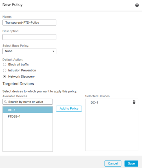
- Click New Policy to create a new policy to be assigned to the transparent FTD.
- Define an appropriate Name.
- Select the Default Action, in this instance we will choose Network Discovery
-
Select the Targeted Devices and Add to Policy.
- Edit the new policy.
- In the Mandatory section, click Add Rule
In this instance we will not block any traffic, rather permit all and log the traffic for analysis.
- Define an appropriate Name.
- Click Logging and select Log at End of Connection
![]()
- Click Save to save the rule.
- Click Save (top right) to save the policy.
- Click Deploy to deploy the policy to the FTD.
Testing/Verification
To confirm traffic is flowing between the FTD’s interfaces correctly, we shall ping from one side to the other.
- On the FMC navigate to Analysis > Unified Events
From the output below we can confirm ICMP ping requests and replies are successfully allowed, we can also determine that OSPF is configured between the switches either side of the transparent FTD.
![]()
Expanding the connection event confirms the connection was permitted by the Transparent-FTD-Policy created earlier, confirming the traffic successfully traversed the Transparent FTD.
![]()
