Cisco FMC/FTD version 7.3 introduced support for Dynamic Virtual Tunnel Interfaces (DVTI). A DVTI allows for a single tunnel configuration on the Hub FTD for connecting to hundreds of spokes, instead of configured 100s of Static VTI’s peer spokes, which simplifies the configuration of the Hub FTD. Like the Cisco IOS-XE FlexVPN solution, the FTD uses a virtual template, this is dynamically cloned, and a virtual access (VA) interface is created when a VPN is established. The Virtual Access interfaces inherits the settings from the virtual template interface. The Virtual Access interface is active on the Hub for the duration of the VPN tunnel between itself and the spoke, once the tunnel is terminated the Virtual Access interface is removed.
This post covers configuring a Hub and Spoke VPN topology, with an FTD acts as the Hub and two spoke devices, another FTD and a CSR1000V router. Both FTD’s will utilise Loopback interfaces for the tunnel interface and run BGP over the VTI.
The following software versions were used:-
- Management – Cisco FMC 7.4.1
- Hub – Cisco FTD 7.4.1
- Spoke 1 – Cisco FTD 7.4.1
- Spoke 2 – CSR1000V 16.6 Router
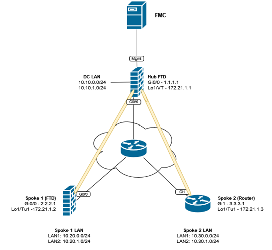
The figure below represents the topology used in this post.
Configuration
This post covers the specific VPN configuration, it is assumed the basic configuration such as interfaces, routing and Access Control rules etc are in place beforehand.
Hub FTD
Complete the following steps from the FMC GUI.
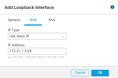
Create a loopback interface
- From the FMC, navigate to Devices > Device Management
- Edit the Hub FTD device
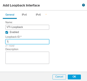
- Click Add Interfaces > Loopback Interface
- Define a suitable Name and Loopback ID

- Click IPv4 and enter an IP Address
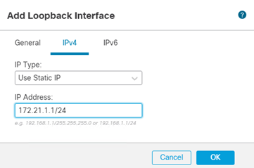
- Click Ok
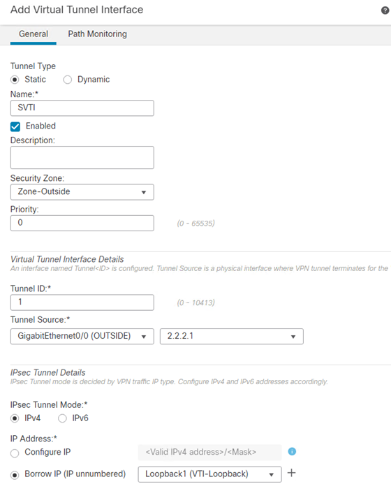
Create a Dynamic Virtual Tunnel Interface
The Hub FTD will be configured with a Dynamic VTI interface, compared to the spokes which will be configured with a Static VTI.
- Click Add Interfaces > Virtual Tunnel Interface
- Select Dynamic
- Enter an appropriate Name.
- Select the Security Zone representing the outside interface.
- Enter a Tunnel ID
- From the Tunnel Source drop-down menu, select the OUTSIDE interface.
- From the Borrow IP (IP unnumbered) drop-down menu, select the Loopback interface created in the previous steps.
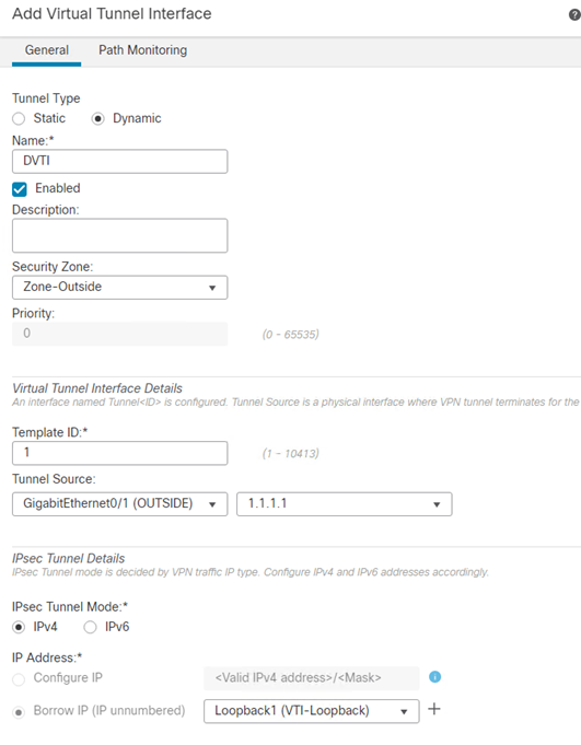
- Click Ok
- Click Save
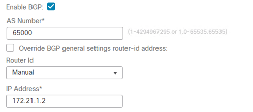
Routing
BGP will be configured between the Hub and the spokes, a BGP neighbor must be configured for each individual BGP peer, as of FTD 7.4.1 BGP peer group ranges are not currently supported.
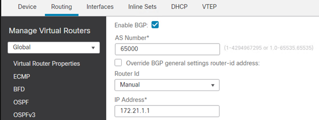
- Navigate to Devices > Device Management > DEVICENAME > Routing > General Settings > BGP
- Select Enable BGP
- Enter the AS number.
- Optional, configure a manual Router ID.
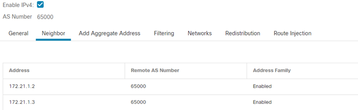
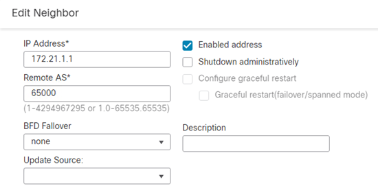
- Click BGP > IPv4 > Neighbor
- Click Add
- Click Enabled address.
- Enter the IP Address and Remote AS of the spoke.
- Click Advanced
- Select Use itself as next hop for this neighbor
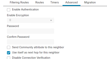
- Click Ok
- Repeat for the remaining Spokes.
- Click Ok
- Click Save
Spoke FTD
Complete the following steps from the FMC GUI.
Create a Loopback Interface
- Navigate to Devices > Device Management
- Edit the Spoke FTD device.
- Click Add Interfaces > Loopback Interface
- Define a suitable Name and Loopback ID
- Click IPv4 and enter an IP Address
- Click Ok
Create a Virtual Tunnel Interface
On the spoke FTD a Static VTI is created.
- Click Add Interfaces > Virtual Tunnel Interface
- Select Static
- Enter an appropriate Name.
- Select the Security Zone representing the outside interface.
- Enter a Tunnel ID
- From the Tunnel Source drop-down menu, select the OUTSIDE interface.
- From the Borrow IP (IP unnumbered) drop-down menu, select the Loopback interface created in the previous steps.
- Click Ok
- Click Save
Routing
BGP will be configured on the Spoke FTD to form an adjacency to the Hub.
- Navigate to Devices > Device Management > DEVICENAME > Routing > General Settings > BGP
- Select Enable BGP
- Enter the AS number.
- Optional, configure a manual Router ID.
- Click BGP > IPv4 > General
- Click Enable IPv4
- Click Neighbor
- Click Add
- Click Enabled address.
- Enter the IP Address and Remote AS of the Hub FTD.
- Click Ok
- Click Advanced
- Select Use itself as next hop for this neighbor

- Click Ok
- Click Networks
- Click Add to advertise the local spoke network.
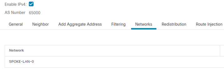
- Click Ok
- Click Save
Site-to-Site VPN Topology
A basic Route Based VPN topology will be created using the Hub and Spoke VTI’s created in the previous steps.
- Navigate to Devices > VPN > Site to Site
- Click +Site to Site VPN to create a VPN topology.
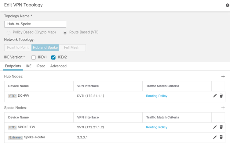
- Define an appropriate Topology Name
- Select Route Based (VTI)
- Select the Network Topology type as Hub and Spoke
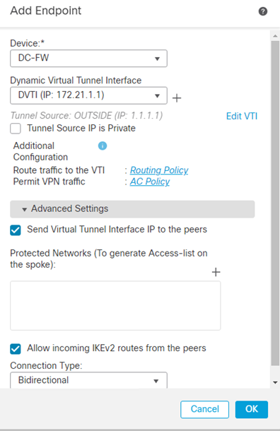
- Add a new Hub Nodes
- Select the Hub FTD and the Dynamic Virtual Tunnel Interface created in the previous step.
- Under Advanced Settings ensure Send Virtual Tunnel Interface IP to the peers and Allow incoming IKEv2 routes from the peers is selected.
NOTE – the option Send Virtual Tunnel Interface IP to the peers setting is important, when enabled this sends a /32 route for the tunnel interface (loopback) IP address to the peer. This /32 route is added to the peers routing table and allows reachability via the correct tunnel interface and is used for establishing a BGP adjacency or if using static routes.
- Click Ok
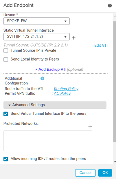
- Add a Spoke Node
- Select the Spoke FTD and the Static Virtual Tunnel Interface created in the previous step.
- Under Advanced Settings ensure Send Virtual Tunnel Interface IP to the peers and Allow incoming IKEv2 routes from the peers is selected.
- Click Ok
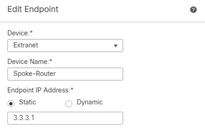
For devices not managed by the FMC such as an ASA, Cisco Router or Third-Party Firewall/Router, the spoke node must be added as an Extranet device.
- Add a Spoke Node
- Select Device as Extranet
- Enter an appropriate Name
- Enter the IP Address of the spoke
- Click Ok
- Click IKE
- Change Authentication Type to Pre-shared Manual Key and enter a complex PSK.
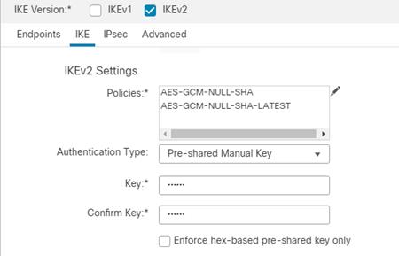
-
Click Save to complete the VPN topology configuration.
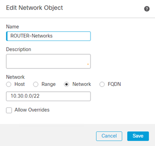
Network Objects
Network objects to represent the Hub and Spoke networks shall be created for later use in the Access Control Policy.
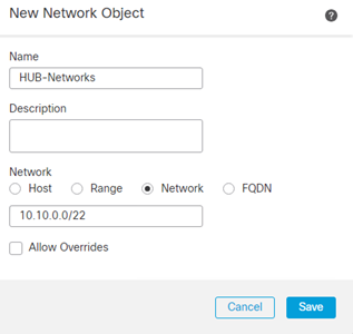
- Navigate to Objects > Object Management > Network
- Click Add Network > Add Object
- Define an appropriate Name, i.e. HUB-Networks
- Select Network as Network
- Repeat for the Spoke FTD Network(s)
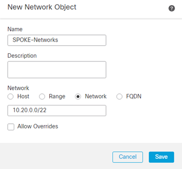
- Repeat for the Spoke Router Network(s)
Access Control Policy
The Access Control Policy should be configured with explicit rules to permit traffic between hub and spoke networks.
- Navigate to Policies > Access Control > Access Control
- Edit the Policy of the Hub
- Click Add Rule
- Specify the Source Network and Destination Network as the objects to represent the Hub and Spoke Networks.
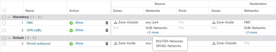
- Click Save
- Repeat the same rules on the Spoke Policy (if different).
With the configuration complete, deploy changes to both the Hub and Spoke FTDs.
Spoke Router
The configuration syntax below represents the Cisco IOS-XE router FlexVPN Static VTI configuration. For more information on configuring FlexVPN refer to these posts.
aaa new-model
aaa authorization network FLEX local
!
crypto ikev2 authorization policy IKEV2-AUTHZ
 route set interface
 route set remote ipv4 172.21.1.3 255.255.255.255
!
crypto ikev2 proposal PROP
 encryption aes-gcm-256 aes-gcm-128
 prf sha512 sha384 sha256 sha1
 group 21 20 19 16 15 14
!
crypto ikev2 policy IKEV2-POLICY
 proposal PROP
!
crypto ikev2 keyring KEYRING
 peer ANY
 address 1.1.1.1
 pre-shared-key local Cisco1234
 pre-shared-key remote Cisco1234
 !
!
crypto ikev2 profile IKEV2-PROFILE
 match identity remote address 1.1.1.1 255.255.255.255
 authentication remote pre-share
 authentication local pre-share
 keyring local KEYRING
 aaa authorization user psk list FLEX IKEV2-AUTHZ
 no config-exchange request
!
crypto ipsec transform-set TSET esp-gcm 256
 mode tunnel
!
crypto ipsec profile IPSEC-PROFILE
 set transform-set TSET
 set ikev2-profile IKEV2-PROFILE
!
interface Loopback0
 ip address 172.21.1.3 255.255.255.255
!
interface Loopback1
 ip address 10.30.0.1 255.255.255.0
!
interface Loopback2
 ip address 10.30.1.1 255.255.255.0
!
interface Tunnel0
 ip unnumbered Loopback0
 ip mtu 1445
 tunnel source GigabitEthernet1
 tunnel mode ipsec ipv4
 tunnel destination 1.1.1.1
 tunnel protection ipsec profile IPSEC-PROFILE
!
router bgp 65000
 bgp log-neighbor-changes
 network 10.30.0.0 mask 255.255.255.0
 network 10.30.1.0 mask 255.255.255.0
 neighbor 172.21.1.1 remote-as 65000
!
ip route 0.0.0.0 0.0.0.0 3.3.3.254
Testing/Verification
When using VTI’s the tunnels should automatically establish, there is no need to generate interesting traffic.
For testing we shall confirm the tunnels are established and BGP routes learnt.
From the Hub
Run show crypto ikev2 sa to confirm IKEV2 SAs have been established to both peers.
> show crypto ikev2 sa

IKEv2 SAs:
Session-id:13, Status:UP-ACTIVE, IKE count:1, CHILD count:1
Tunnel-id Local Remote fvrf/ivrf Status Role
30208921 1.1.1.1/500 2.2.2.1/500 Global/Global READY RESPONDER
Encr: AES-GCM, keysize: 256, Hash: N/A, DH Grp:21, Auth sign: PSK, Auth verify: PSK
Life/Active Time: 86400/1634 sec
Child sa: local selector 0.0.0.0/0 - 255.255.255.255/65535
remote selector 0.0.0.0/0 - 255.255.255.255/65535
ESP spi in/out: 0x554abd85/0x5de41734

IKEv2 SAs:

Session-id:15, Status:UP-ACTIVE, IKE count:1, CHILD count:1
Tunnel-id Local Remote fvrf/ivrf Status Role
 33910743 1.1.1.1/500 3.3.3.1/500 Global/Global READY RESPONDER
 Encr: AES-GCM, keysize: 256, Hash: N/A, DH Grp:21, Auth sign: PSK, Auth verify: PSK
Life/Active Time: 86400/166 sec
Child sa: local selector 0.0.0.0/0 - 255.255.255.255/65535
remote selector 0.0.0.0/0 - 255.255.255.255/65535
ESP spi in/out: 0xf089ee36/0xadb75585
Run show bgp on the hub to confirm the BGP routes from the two peer tunnels.
> show bgp

BGP table version is 36, local router ID is 172.21.1.1
Status codes: s suppressed, d damped, h history, * valid, > best, i - internal,
 r RIB-failure, S Stale, m multipath
Origin codes: i - IGP, e - EGP, ? - incomplete
 Network Next Hop Metric LocPrf Weight Path
*> 10.10.1.0/24 10.10.0.1 0 32768 i
*> 10.10.2.0/24 10.10.0.1 0 32768 i
*>i10.20.0.0/24 172.21.1.2 0 100 0 i
*>i10.30.0.0/24 172.21.1.3 0 100 0 i
*>i10.30.1.0/24 172.21.1.3 0 100 0 i
Run show route confirms BGP routes have been learnt from Spoke 1 (FTD) and from Spoke 2 (Router), the VTI /32 loopback interface IP address from both spokes appear as VPN routes.
> show route
Gateway of last resort is 1.1.1.254 to network 0.0.0.0
S* 0.0.0.0 0.0.0.0 [1/0] via 1.1.1.254, OUTSIDE
C 1.1.1.0 255.255.255.0 is directly connected, OUTSIDE
L 1.1.1.1 255.255.255.255 is directly connected, OUTSIDE
C 10.10.0.0 255.255.255.0 is directly connected, inside
L 10.10.0.254 255.255.255.255 is directly connected, inside
S 10.10.1.0 255.255.255.0 [1/0] via 10.10.0.1, inside
S 10.10.2.0 255.255.255.0 [1/0] via 10.10.0.1, inside
B 10.20.0.0 255.255.255.0 [200/0] via 172.21.1.2, 00:37:25
B 10.30.0.0 255.255.255.0 [200/0] via 172.21.1.3, 00:40:47
B 10.30.1.0 255.255.255.0 [200/0] via 172.21.1.3, 00:40:47
C 172.21.1.0 255.255.255.0 is directly connected, VTI-Loopback
L 172.21.1.1 255.255.255.255 is directly connected, VTI-Loopback
V 172.21.1.2 255.255.255.255 connected by VPN (advertised), DVTI_va34
V 172.21.1.3 255.255.255.255 connected by VPN (advertised), DVTI_va35
S 192.168.0.0 255.255.0.0 [1/0] via 10.10.0.1, inside
From the spoke FTD
Confirm the IKEv2 SA have been established, run show crypto ikev2 sa detail. From the output below we can confirm the IKEv2 SA have been established and the Hub’s loopback /32 IP address has been sent and received by the spoke as part of the SA exchange.
> show crypto ikev2 sa detail

IKEv2 SAs:

Session-id:4, Status:UP-ACTIVE, IKE count:1, CHILD count:1

Tunnel-id Local Remote fvrf/ivrf Status Role
15331893 2.2.2.1/500 1.1.1.1/500 Global/Global READY INITIATOR
Encr: DES, Hash: SHA96, DH Grp:14, Auth sign: PSK, Auth verify: PSK
Life/Active Time: 86400/3302 sec
Session-id: 4
Status Description: Negotiation done
Local spi: 6336F8C0EAA4C62C Remote spi: 8F9B973B32FEEB3C
Local id: 2.2.2.1
Remote id: 1.1.1.1
Local req mess id: 88 Remote req mess id: 146
Local next mess id: 88 Remote next mess id: 146
Local req queued: 88 Remote req queued: 146
Local window: 1 Remote window: 1
DPD configured for 10 seconds, retry 2
NAT-T is not detected
IKEv2 Fragmentation Configured MTU: 576 bytes, Overhead: 28 bytes, Effective MTU: 548 bytes
VTI Interface: SVTI / Tunnel1
 Remote subnets:
172.21.1.1 255.255.255.255

Parent SA Extended Status:
Delete in progress: FALSE
Marked for delete: FALSE
Child sa: local selector 0.0.0.0/0 - 255.255.255.255/65535
remote selector 0.0.0.0/0 - 255.255.255.255/65535
To confirm whether the data plane IPSec SA have been established, run show crypto ipsec sa. From the output below we can confirm the SA have been established between the two peers and the encaps|decaps counters are increasing, indicating bidirectional traffic flow.
 > show crypto ipsec sa

interface: SVTI
Crypto map tag: __vti-crypto-map-Tunnel1-0-1, seq num: 65280, local addr: 2.2.2.1

Protected vrf (ivrf): Global
local ident (addr/mask/prot/port): (0.0.0.0/0.0.0.0/0/0)
remote ident (addr/mask/prot/port): (0.0.0.0/0.0.0.0/0/0)
current_peer: 1.1.1.1


#pkts encaps: 231, #pkts encrypt: 231, #pkts digest: 231
#pkts decaps: 227, #pkts decrypt: 227, #pkts verify: 227
#pkts compressed: 0, #pkts decompressed: 0
#pkts not compressed: 231, #pkts comp failed: 0, #pkts decomp failed: 0
#pre-frag successes: 0, #pre-frag failures: 0, #fragments created: 0
#PMTUs sent: 0, #PMTUs rcvd: 0, #decapsulated frgs needing reassembly: 0
#TFC rcvd: 0, #TFC sent: 0
#Valid ICMP Errors rcvd: 0, #Invalid ICMP Errors rcvd: 0
#send errors: 0, #recv errors: 0

local crypto endpt.: 2.2.2.1/500, remote crypto endpt.: 1.1.1.1/500
path mtu 1500, ipsec overhead 58(36), media mtu 1500
PMTU time remaining (sec): 0, DF policy: copy-df
ICMP error validation: disabled, TFC packets: disabled
current outbound spi: 18AFAC94
current inbound spi : BAF49883
To confirm the BGP routes have been learnt over the Tunnel interface, run show route.
> show route

Gateway of last resort is 2.2.2.254 to network 0.0.0.0

S* 0.0.0.0 0.0.0.0 [1/0] via 2.2.2.254, OUTSIDE
C 2.2.2.0 255.255.255.0 is directly connected, OUTSIDE
L 2.2.2.1 255.255.255.255 is directly connected, OUTSIDE
B 10.10.0.0 255.255.255.0 [200/0] via 172.21.1.1, 00:30:28
B 10.10.1.0 255.255.255.0 [200/0] via 172.21.1.1, 00:18:47
C 10.20.0.0 255.255.255.0 is directly connected, INSIDE
L 10.20.0.1 255.255.255.255 is directly connected, INSIDE
S 10.20.1.0 255.255.255.0 [1/0] via 10.20.0.2, INSIDE
S 10.20.2.0 255.255.255.0 [1/0] via 10.20.0.2, INSIDE
C 172.21.1.0 255.255.255.0 is directly connected, SVTI
V 172.21.1.1 255.255.255.255 connected by VPN (advertised), SVTI
L 172.21.1.2 255.255.255.255 is directly connected, SVTI
From the Spoke Router
Run show crypto ikev2 sa to confirm IKEV2 SAs have been established to the hub.
RTR#show crypto ikev2 sa

IPv4 Crypto IKEv2 SA

Tunnel-id Local Remote fvrf/ivrf Status
1 3.3.3.1/500 1.1.1.1/500 none/none READY
Encr: AES-GCM, keysize: 256, PRF: SHA512, Hash: None, DH Grp:21, Auth sign: PSK, Auth verify: PSK
Life/Active Time: 86400/1516 sec
Run show ip route confirms the Hub’s BGP routes learnt via the Tunnel interface.
CSR#show ip route

Gateway of last resort is 3.3.3.254 to network 0.0.0.0
S* 0.0.0.0/0 [1/0] via 3.3.3.254
 3.0.0.0/8 is variably subnetted, 2 subnets, 2 masks
C 3.3.3.0/24 is directly connected, GigabitEthernet1
L 3.3.3.1/32 is directly connected, GigabitEthernet1
 10.0.0.0/8 is variably subnetted, 6 subnets, 2 masks
B 10.10.1.0/24 [200/0] via 172.21.1.1, 00:39:19
B 10.10.2.0/24 [200/0] via 172.21.1.1, 00:39:19
C 10.30.0.0/24 is directly connected, Loopback1
L 10.30.0.1/32 is directly connected, Loopback1
C 10.30.1.0/24 is directly connected, Loopback2
L 10.30.1.1/32 is directly connected, Loopback2
 172.21.0.0/32 is subnetted, 2 subnets
S 172.21.1.1 is directly connected, Tunnel0
C 172.21.1.3 is directly connected, Loopback0
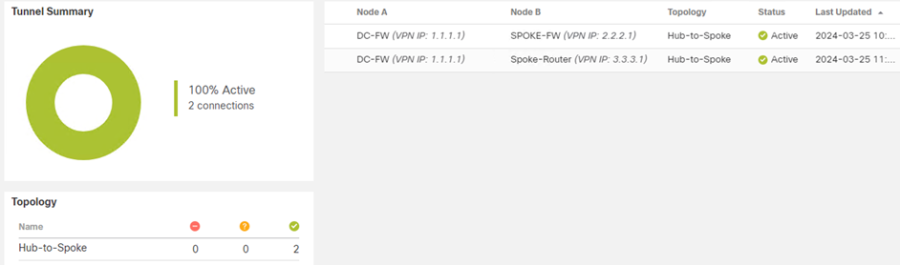
From the FMC
The FMC GUI will also provide information on the state of the VPN tunnels.
- From the FMC navigate to Overview > Site to Site VPN
From the output below we can confirm the VPN tunnel is up between the three peers.
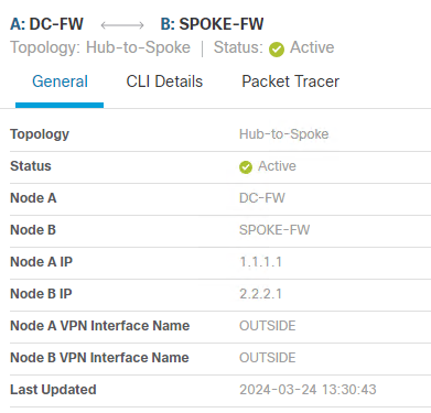
- Hover the mouse of the tunnel and click View full information when this appears.
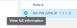
The General tab will provide information about the Nodes in the VPN Topology
- Click CLI Details, this will provide detailed information about the VPN for troubleshooting purposes.
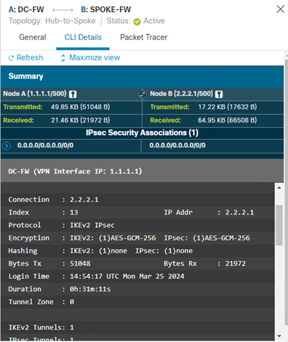
NOTE – show commands cannot be run on unmanaged (extranet) devices.
